基于STM32的猪舍环境自动监控系统的设计 硕士论文

摘 要
本文结合生猪养殖要求和猪舍环境特点,在查阅了大量中英文献的基础上, 总结出了影响猪只生长发育的四大环境因子――温度、湿度、通风、光照,同时 对猪舍环境控制技术的历史发展和现状有了清晰的认识。
首先深入企业调查猪场存在的实际问题和征询管理人员的需求,同时从工作 人员那里了解小猪的生长曲线及不同阶段的猪最适宜的成长环境;之后提出系统 总体构思,草拟了几个可行性方案,经过比对、甄别,筛选出了最佳方案;最后 完成了硬件电路的设计及软件设计(基于库函数的开发环境)。经过模拟测试, 主控制器能精确地测量各环境变量,并实现对多种输出设备的控制。
本文将现代控制理论、传感器技术、微电子技术等综合运用,研究出了一套 用于生猪规模化养殖的环境监控系统。该系统通过传感器采集各环境因子的实时 值,将其送入到控制器 STM32,经过与预设值分析比对后,遵循事先制定的控 制策略,发出控制信号,驱动相关的执行设备,从而达到控制参数的目的,营造 出一个舒适的猪舍环境。此外,这些值通过 CAN 总线上传到办公室端的主机中, 方便管理人员通过人机交互界面实时查看这些量,并能根据需要随时调整各参数 限值,以适应不同阶段的猪对环境的要求。
关键词:猪舍环境,自动监控,STM32,CAN,传感器
I
ABSTRACT
Combining with the requirements of pig breeding and characteristics of piggery environment, on the basic of consulting a lot of Chinese and English literatures, this thesis summarizes four major environmental factors -- temperature, humidity, ventilation, light -- affecting the growth and development of pig, has also a preliminary understanding of the historical development and current situation of environmental control technology.
Firstly, investigates the actual existing problems through accessing in-depth farm enterprises and consults managerial staffs' personnel needs, at the same time, achieves the porkets' growth curve and the most appropriate growth environment of different stages of pig. Secondly, puts forward the system's overall outline, draws up some feasible plans, through comparison and analysis, screening out the best scheme. Finally, completes the hardware circuit design, the software design based on the development environment of library function. After the actual test, the main controller can accurately measure the environmental variables, to realize the control of a variety of output devices.
On the basic of the comprehensive application of sensor technology, modern control theory and microelectronic technology, this thesis developed a set of environmental monitoring system for large-scale pig breeding. The system gathers real time value of each environmental factor through the sensor, will sent them to STM32 controller, after analysis and comparison with the preset value, following the control strategy has been fixed in advance, generates a control signal to drive the related implementing equipment, so as to achieve the purpose of control parameters, create a comfortable piggery environment. In addition, these values through the CAN bus to upload to the host of office end, to facilitate the administrative staffs can real-time view of these quantities through the man-machine interface, and can adjust each parameter's limited values according to the need at any time, in order to adapt to the demands on the environment at different stages of swine.
Keywords: piggery environment, automatic monitoring, STM32, CAN, sensor
II
目录
1.1 课题的研究背景和意义.........................................................................1
1.2 猪舍环境控制技术国内外的发展历程及现状.....................................3
1.3 本课题的研究内容.................................................................................6
1.4 本课题研究的关键问题.........................................................................7
2.1 系统的设计任务.....................................................................................8
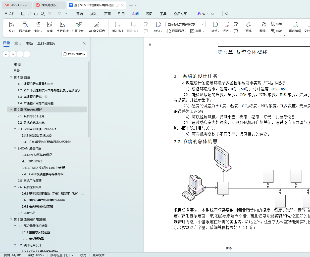
2.2 系统的总体构思.....................................................................................8
2.3 控制器和通信总线的选择.....................................................................9
2.3.1 控制器/系统比较 ........................................................................9
2.3.2 几种常见的长距离通讯总线比较............................................11
2.5 系统工作原理.......................................................................................24
2.6 系统控制策略.......................................................................................25
2.6.2 舍内有毒气体浓度控制策略....................................................25
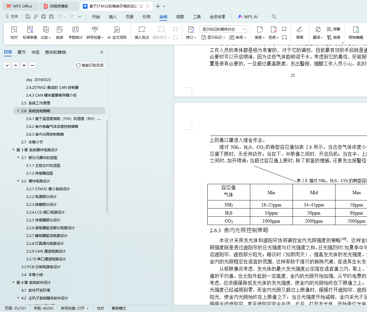
2.6.3 舍内光照控制策略....................................................................26
3.1 部分元器件的选型...............................................................................27
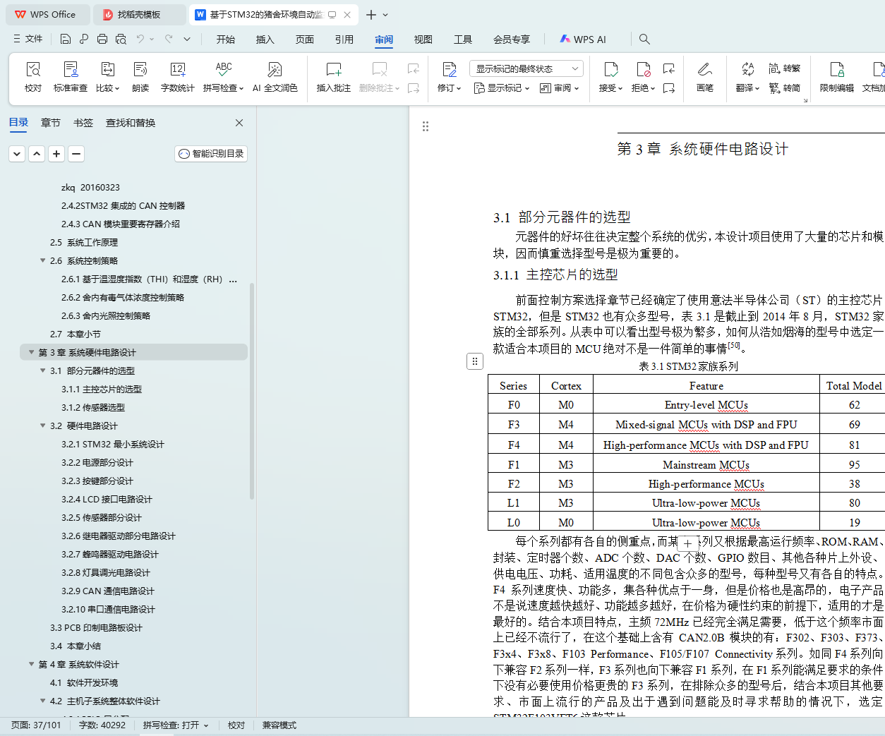
3.1.1 主控芯片的选型........................................................................27
3.1.2 传感器选型................................................................................28
3.2 硬件电路设计.......................................................................................30
III
 3.2.2 电源部分设计............................................................................33
3.2.3 按键部分设计............................................................................34
3.2.5 传感器部分设计........................................................................37
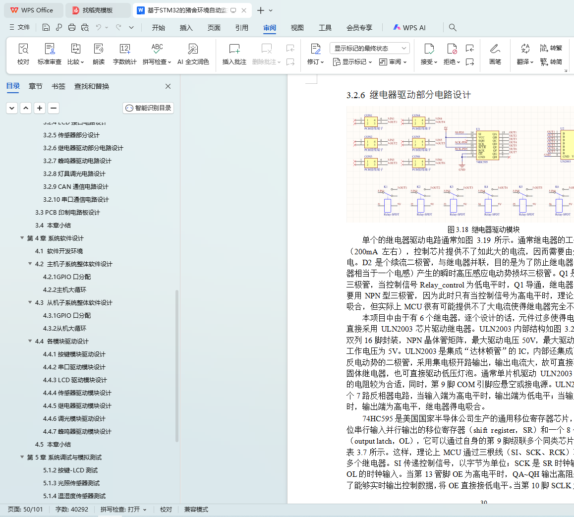
3.2.6 继电器驱动部分电路设计........................................................39
3.2.7 蜂鸣器驱动电路设计................................................................41
3.2.8 灯具调光电路设计....................................................................41
3.2.10 串口通信电路设计..................................................................43
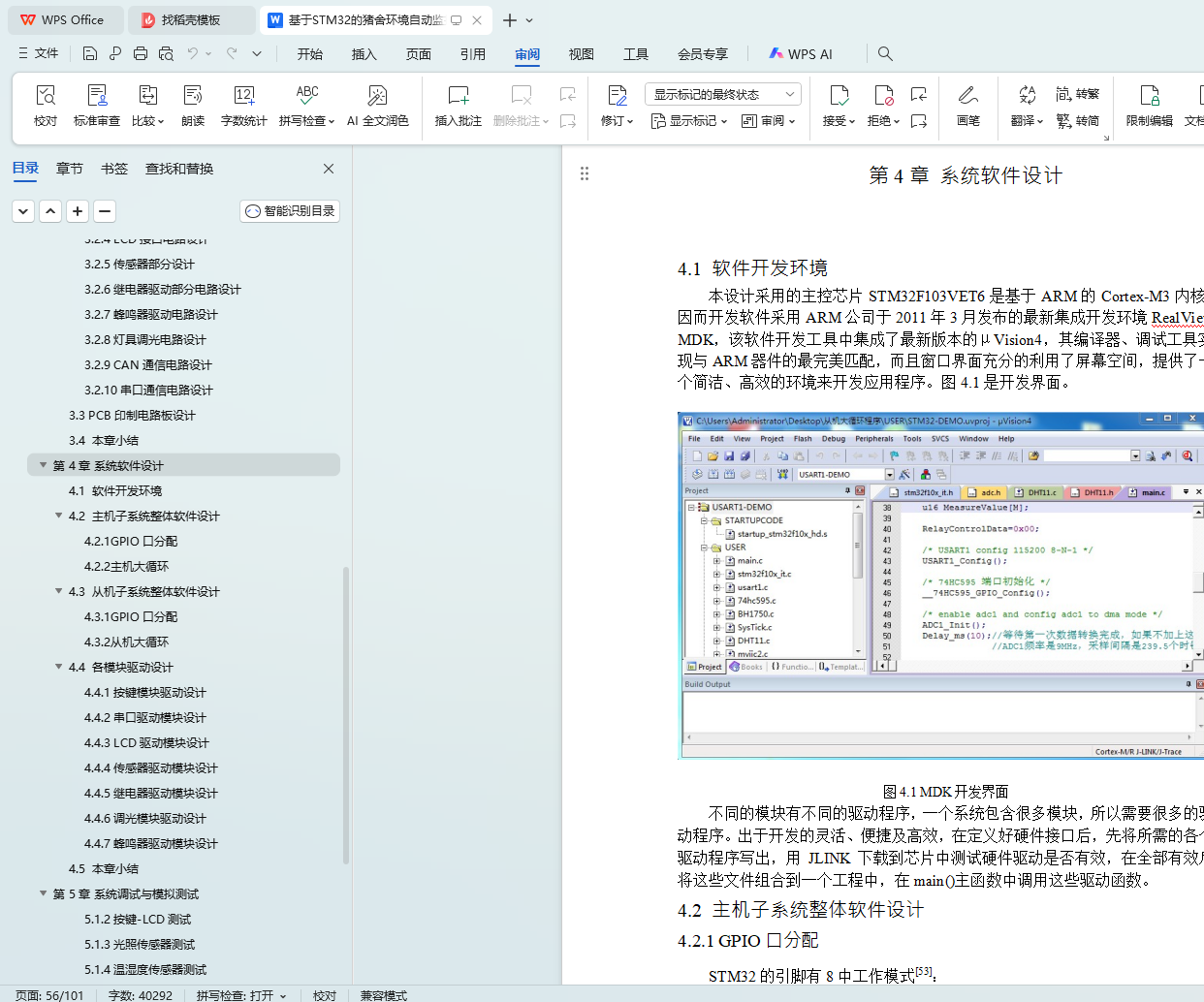
4.1 软件开发环境.......................................................................................45
4.2 主机子系统整体软件设计...................................................................45
4.2.2 主机大循环................................................................................46
4.3 从机子系统整体软件设计...................................................................48
4.3.2 从机大循环................................................................................48
4.4 各模块驱动设计...................................................................................49
4.4.1 按键模块驱动设计....................................................................49
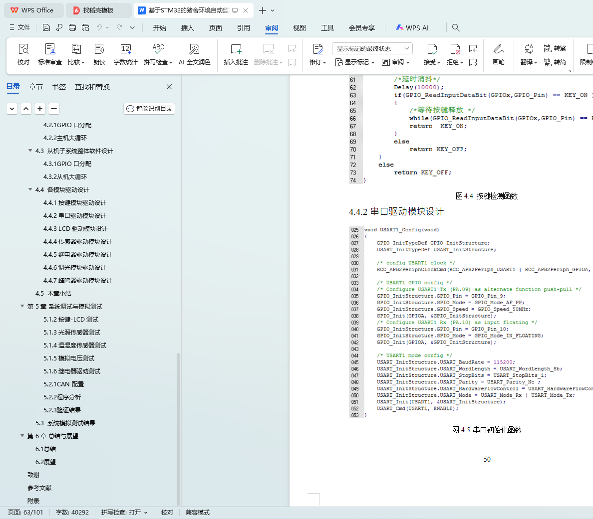
4.4.2 串口驱动模块设计.....................................................................50
4.4.4 传感器驱动模块设计................................................................53
4.4.5 继电器驱动模块设计................................................................58
4.4.6 调光模块驱动设计....................................................................60
4.4.7 蜂鸣器驱动模块设计................................................................61
5.1.1 串口测试....................................................................................63
5.1.3 光照传感器测试........................................................................64
5.1.4 温湿度传感器测试....................................................................65
IV
 5.1.5 模拟电压测试............................................................................65
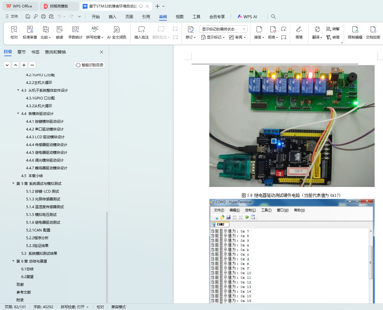
5.1.6 继电器驱动测试........................................................................66
5.2.2 程序分析....................................................................................71
5.2.3 验证结果....................................................................................74
5.3 系统模拟测试结果...............................................................................75